
FT-891 Headset Adapter for Yamaha CM500
A bespoke adapter custom built to fit the characteristics of the CM500.

The Yamaha CM500
I picked up a set of CM500 headphones when I brought my Flexradio station online. They came recommended from a number of folks on the Flexradio forums. At the time the price was only $60 representing a good combination of price and performance.
I ended up building an adapter recommended by those good folks had had a good experience using the headset with the Flex.
The Yaesu FT-891
By that point I had already begun doing a good number of POTA activations. For audio I had been using a set of earbuds connected to the rig and the stock mic. However, winter was coming and I wanted something that would allow me to more easily keep my hands warm.
I surmised that a proper headset and a PTT foot switch would do the trick. But given the voltage differences between the mic connector on the FT-891 (+5v) and the Flex (+3v) I knew I would have to wire up something different.
The internet is full of schematics from people creating adapters FT-891 adapters for their Heil headsets. I built one of those first, but ran into problems (can no longer find the design), so I began tweaking. This post serves to document what I ended up with.
The Schematic
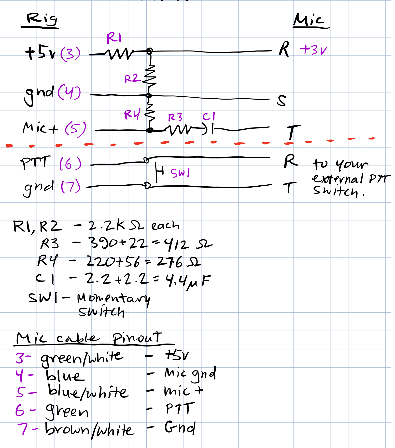
Notes
You can fiddle with resistor values. I think calculations originally called for for 415 and 275 ohms for R3 and R4, but I didn’t have any of those sitting around. Likewise, I would have preferred a single 4.7 uF cap, but I didn’t have one of those either.
My schematic includes a momentary switch mounted to the perf board so that I don’t have to rely on an external switch to be connected.
You’re really dealing with two circuits here. The bottom is for PTT. The top is for the microphone.
You can chose the wiring for the right hand side of the PTT connector (which wires to assign to T, R or S). Just make sure your switch wiring matches when you wire up the male end.
The switch is completely optional. I just wanted an easy way to test PTT without having to plug something in. I also figure it might be handy in the field. (To date, I have never used it. 😁)
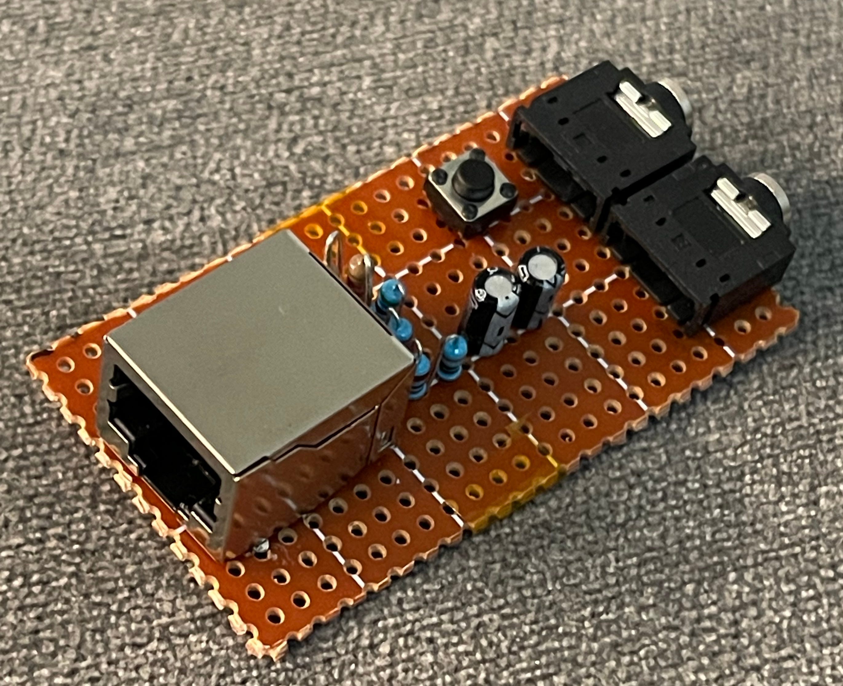
The Build
I ended up putting the whole thing on a perf board, then fitted the perf board into a custom designed 3D printed case.
I had the following on hand that I wanted to incorporate:
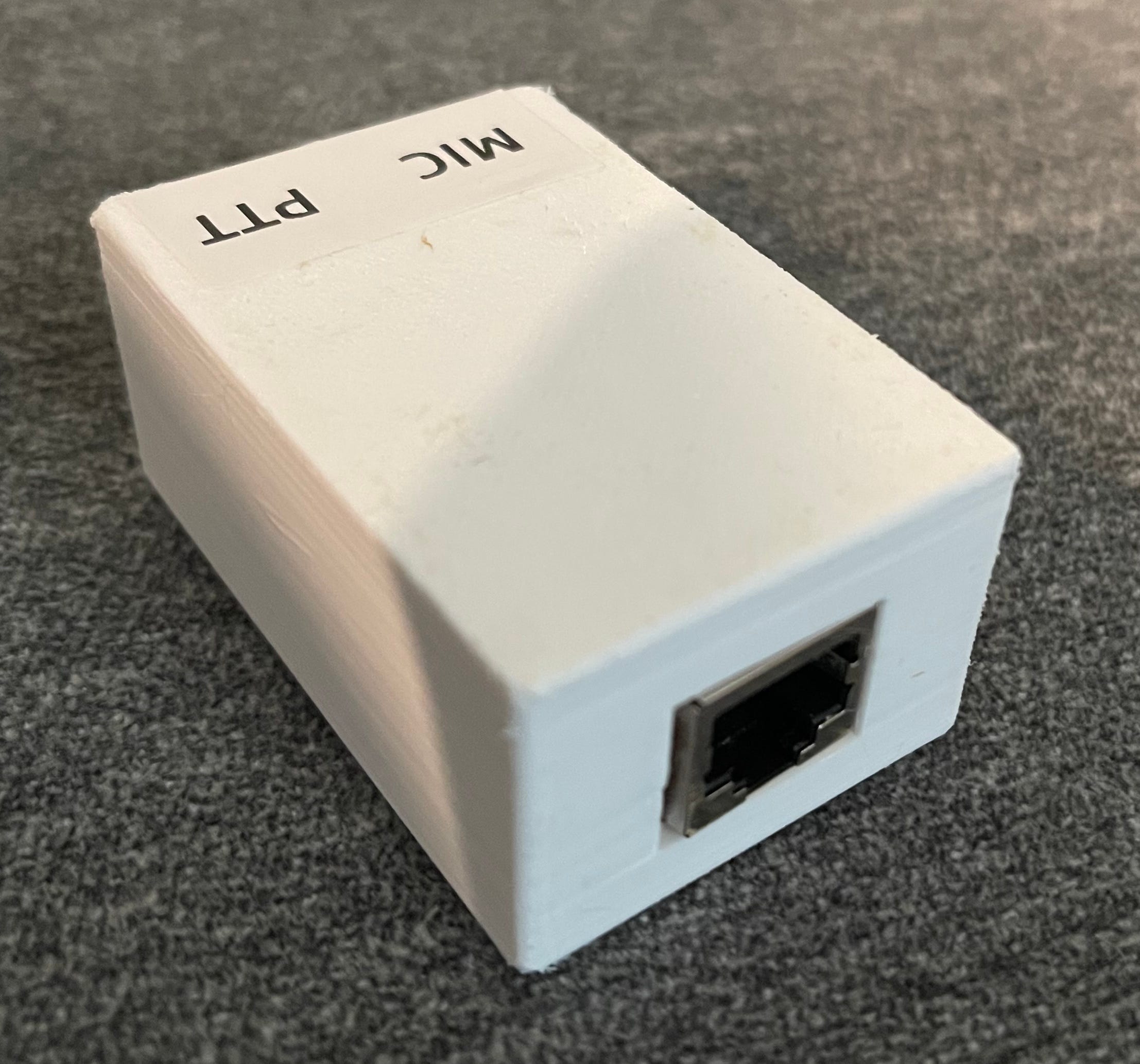
RJ45 right angle solder chassis mount - Inconvenient because the pins are offset and DO NOT line up with the holes on the perfboard. You end up having to force them to fit. Because of that, you need to MAKE SURE to solder down the anchor tabs to the PCB or use some kind of adhesive.
1/8” TRS connectors - these fit right into the perf board.
The 3D printed case is designed so that you just snap the PCB in. No tabs, screws or anything like that. (Tinkercad case)
Here are some pictures of the build:
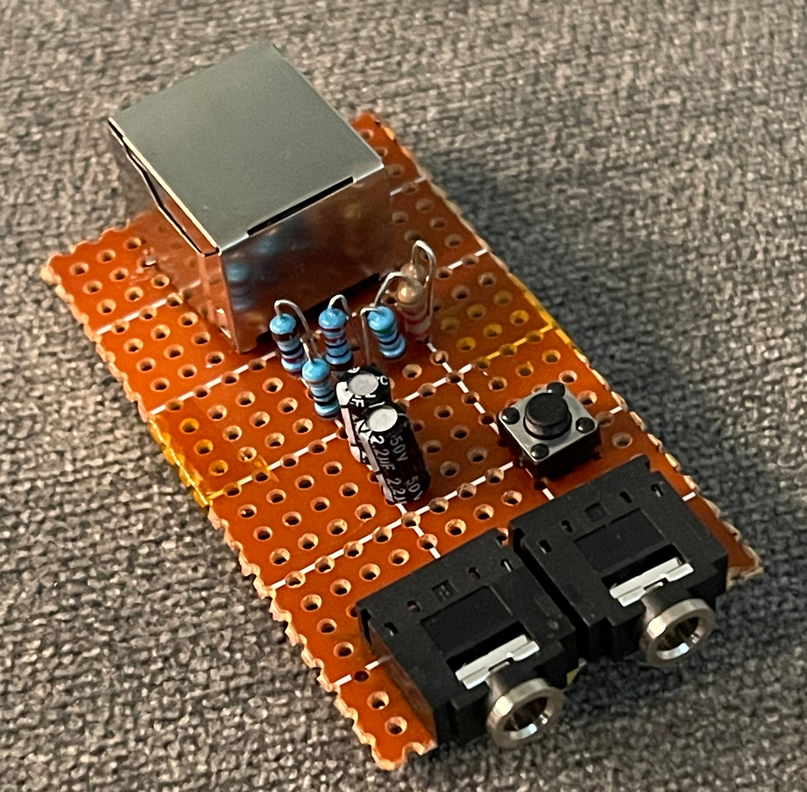
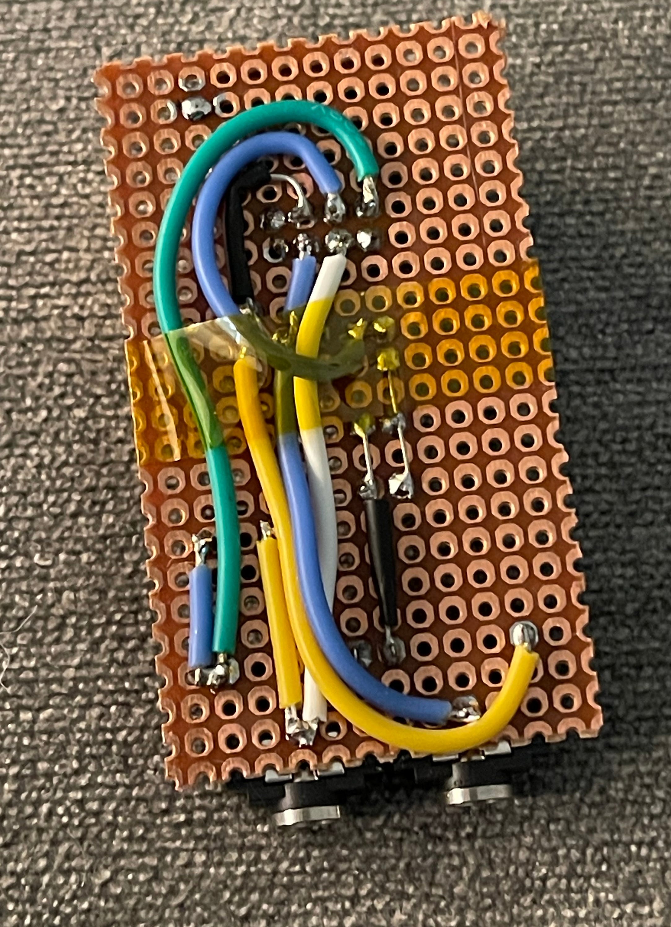
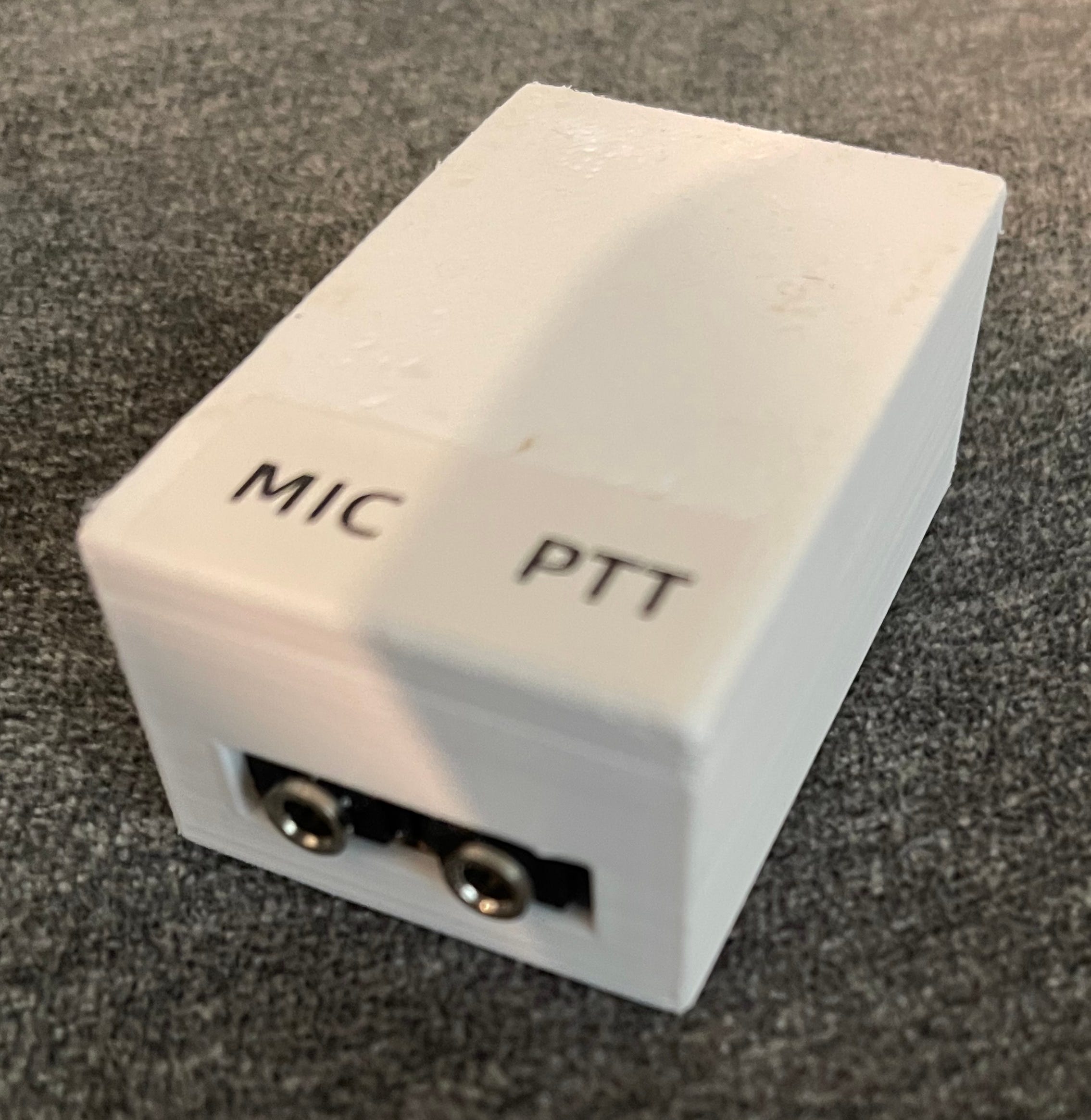
Apologies for the sloppiness of the wiring. I still haven’t figure out how everybody else manages such tidy builds.
I’ve been using this for over a year now with dozens of activations. It does the job well.