
Concept: Trapped Vertical for 10, 15 and 20 Meters
I wanted a no-tune, no-adjustment antenna for use with my QDX and x6100.

My Quest for SO2R
I now own two QDX digital transceivers. One is built for the low bands, the other is built for the high bands. I thought it might be really cool to go out and do a SO2R (single operator, two radios) digital POTA activation using these rigs.
For the low band QDX I have a nice tri-band vertical antenna for 30, 40 and 20 meters from QRP guys that is only 17-ish feet tall. It operates by switching one of two loading coils in or out of the antenna. It’s nice because it works and it’s compact. But messing around with those switches requires me to get up and makes it difficult to do unattended multi-band WSPR beaconing and the like. And heaven knows I didn’t get into ham radio for the exercise…
For the high band QDX, I wanted something a little different. My goals were modest. I wanted a single antenna that:
Could work on 10, 15 and 20 meters.
Would not need a tuner.
Would not require adjustment to change bands.
Can handle 10 watts.
Could be deployed using a fishing pole.
Simple ask, right?
It’s a Trap!

One of the first [good] antennas I ever built was a trap dipole for 40 and 20 meters. It lived outside in a permanent deployment. It used stainless steel screws and heavy duty THHN 14 gauge stranded copper. The traps used air-coil inductors made from the same wire around 3/4” PVC. The capacitors were monstrous heavy duty 6kv 27pF ceramic film jobs. They looked scary.
That thing sat out in the Texas sun logging QSOs for about a year before one of the caps died. I replaced that and put it back into service. It’s been a great performer. I still have it, though it’s no longer in use.
Bottom line: I knew that traps worked, and that it should lend itself well to a vertical. So there… I was going to build a trapped vertical.
A trap is simply a capacitor (C) wired in parallel with an inductor (L). Depending the L and C values a trap will resonate at a particular frequency. At frequencies below the resonant frequency the trap acts as a inductor (loading coil, or inductive reactance). At frequencies above the resonant frequency, the reactance is capacitive, which has the effect of blocking RF.
Remember that: resonant frequency, inductive (lengthening) below, capacitive (blocking) above.
I’ve been told that you can simply add traps to the end of antennas to simply block lower and lower frequencies. There are some caveats, sure, but this isn’t a bad way to build a multi-band no-tune antenna.
So I set out to ask the Google how to build a 10/15/20 meter trapped vertical antenna. Well… if someone has already done this, they sure didn’t do a good job of writing it up.
Determining L and C
I had a difficult time initially using the internet how to come up with optimal values of L and C for a given frequency. In fact, consensus seemed to be that you could pick any capacitor you had laying around in your junk drawer. (I don’t think this is true in theory or practice.)
I decided to consult my oracle (a 1988 edition of the ARRL Handbook). There on page 33-7 it lists the formulas required to compute optimal L and C. However, it starts with this little gem before giving the formulas: “The rule of thumb for choosing the coil and capacitor values for traps is based on a reactance of approximately 200 ohms…”, Then:
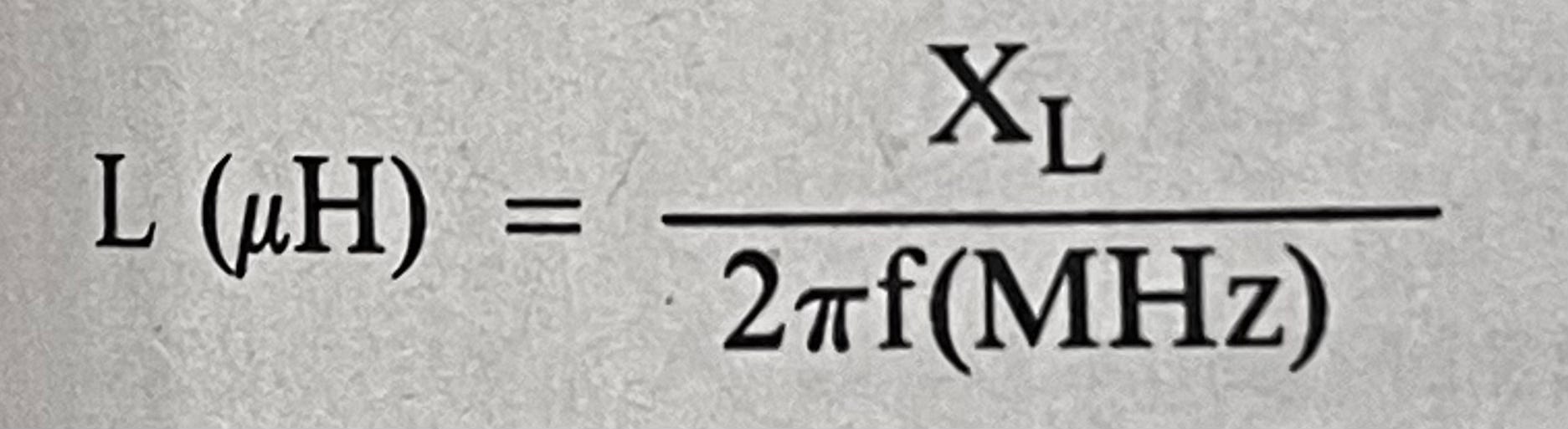

We know that at resonance XL = XC, so solving for L and C should be pretty straightforward. It turns out this calculator does it for you. (Remember that these formulas give you micro henries and micro farads. So you want pico, you need to multiply by one million.)
Here’s a table of all the optimal L and C values for the low sides of each band 20 meters and up:
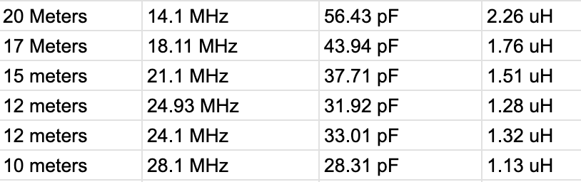
It turns out that in my junk box I have a bunch of 27pF capacitors and a bunch of 10pf capacitors, so I ended up selecting values of 37pF for 15 meters and 27pF for 10 meters. Both are reasonably close, but yielded slightly different reactances:
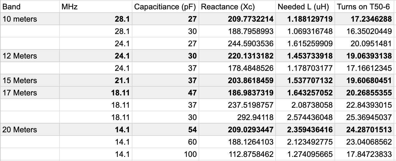
Using Toroids
Knowing that a few websites sell them (sotabeams, qrpguys), I decided to create my inductors using T50-6 toroids. (Actually, I have a long and sordid story in which I try to create some air-coil inductors, but that will be the subject of another post.) That last link contains a good calculator that will get you in the right ballpark for number of turns required to achieve the right inductance.
Wires and Such
All that’s left is wiring things up. I’m going to leave that for another post. But the general idea is to:
Start with a ground plane.
Cut and add a vertical segment for the band you want,
Add a trap for that band.
Measure and adjust for resonance.
Go back to step 2 if you want more bands.
Stay turned for Part 2: the next post will have full build instructions for my antenna.