
Build: Trapped Vertical for 10, 15 and 20 Meters (QRP)
Let's build a no-tune, no-adjustment antenna for use with my QDX and x6100.

The Idea
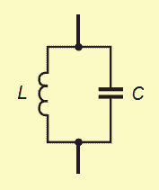
I ended the last post with the general idea for how to build a trapped vertical:
Start with a ground plane.
Cut and add a vertical segment for the band you want,
Add a trap for that band.
Measure and adjust for resonance.
Go back to step 2 if you want more bands.
Remember: the bands we’re interested in are 10, 15 and 20 meters.
Supplies
Some kind of winder to store the thing on (see my ideas below).
A chassis mount BNC connector that has a solderable tab for the ground connection.
2x 3/4” #6 screws.
4x #6 washers.
2x #5 lock washers.
2x #6 nuts
2x #6 butterfly nuts.
Roughly 44 feet of 24 gauge antenna wire. (Length is going to vary depending one the velocity factor of the wire you choose. This antenna was built using BNTECHGO 24 gauge stranded silicone coated wire.
2x T50-6 toroids (yellow on one side)
32 inches of 20 AWG enameled magnet wire. I like this stuff from Remington Wire.
1x 30pF 1kv mica capacitor (I used 3x 10pF caps in parallel).
1x 37pF 1kv mica capacitor (I used a 27pF wired in parallel with a 10pF cap).
4x 14-16 (blue collar) AWG crimp ring terminals with the collar removed.
As much shrink tube of various sizes that you think you’ll need to build things to your standard. I didn’t keep track of the sizes, but most makers have tons of this stuff on hand.
You’ll also need a few tools: wire cutter, wire stripper, solder iron and something to measure SWR (antenna analyzer or Nano VNA).
Here’s a diagram for those of you too impatient to read the full instructions:
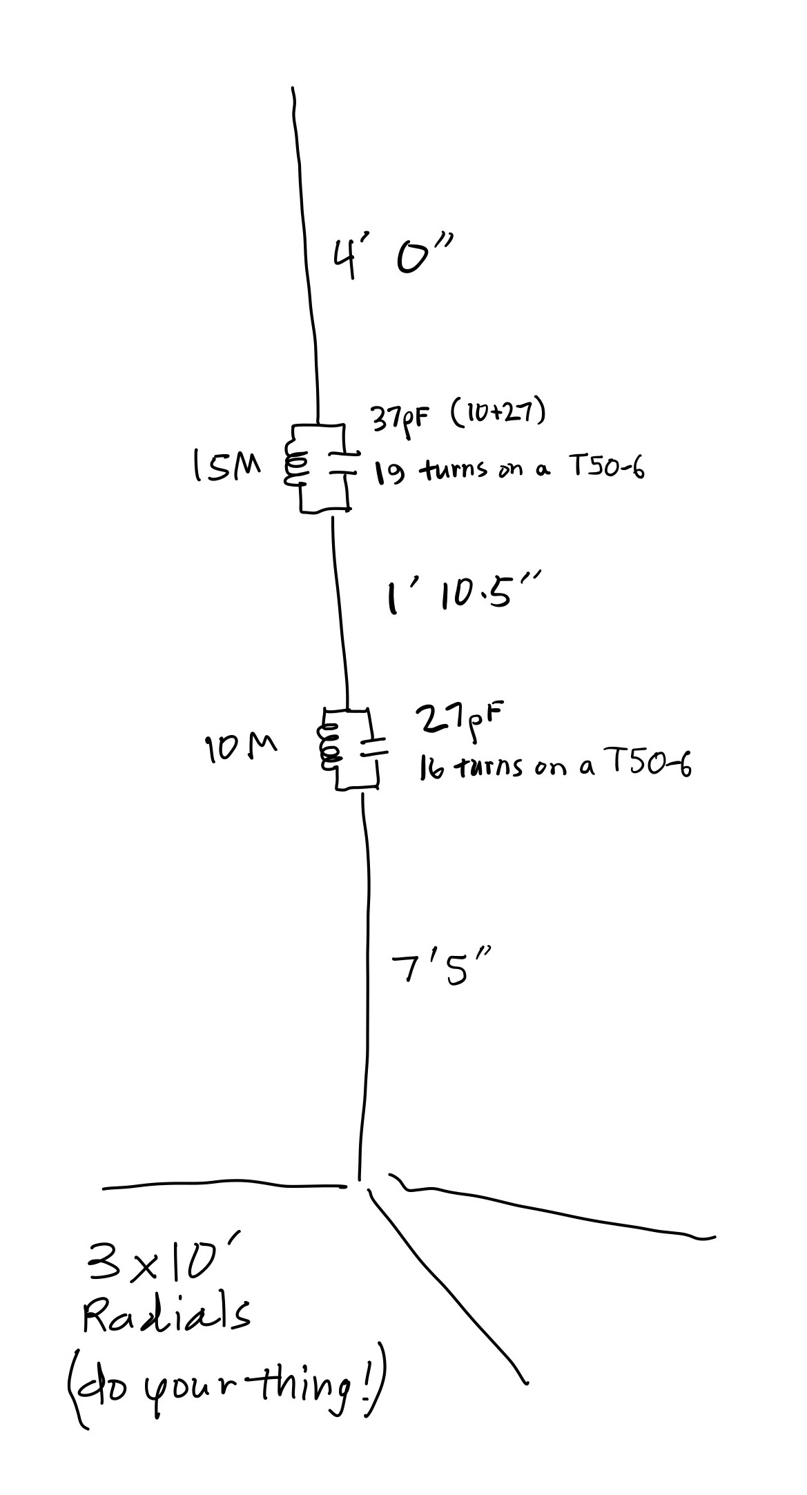
NOTE: This size of toroid and wire suggests you shouldn’t plan on sending more than 10 watts through it.
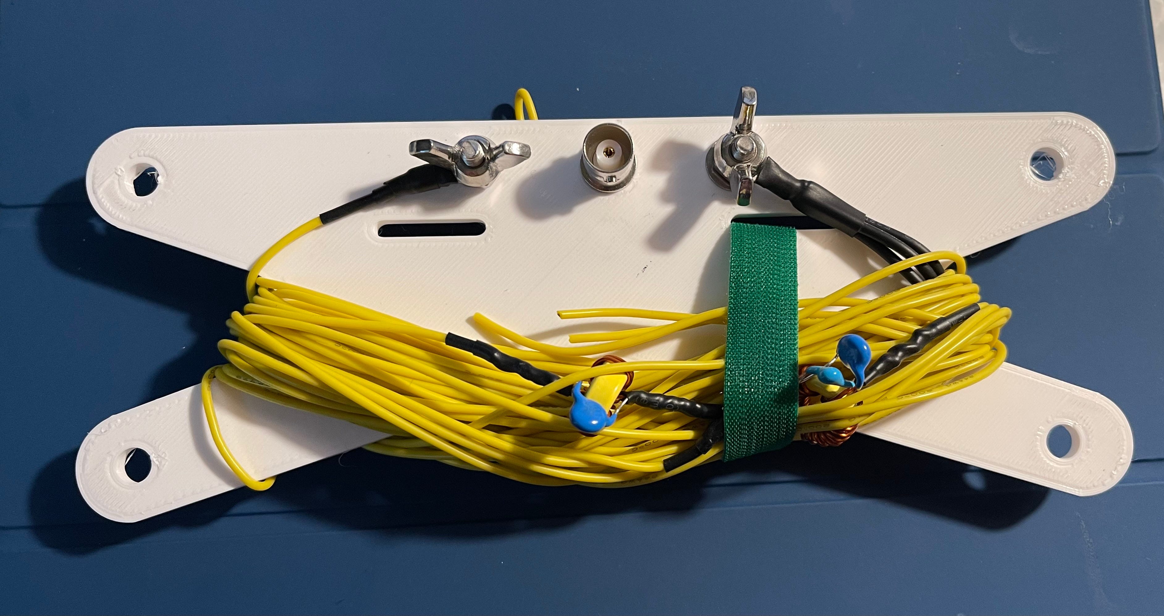
Storage - My Very Own Wire Winder
Up until now I’ve been using a variant of this wire winder I found on Thingiverse. It’s adequate, but it’s tricky to scale and there are one or two things about its construction that annoy me (the reinforcing rails don’t line up 100%).
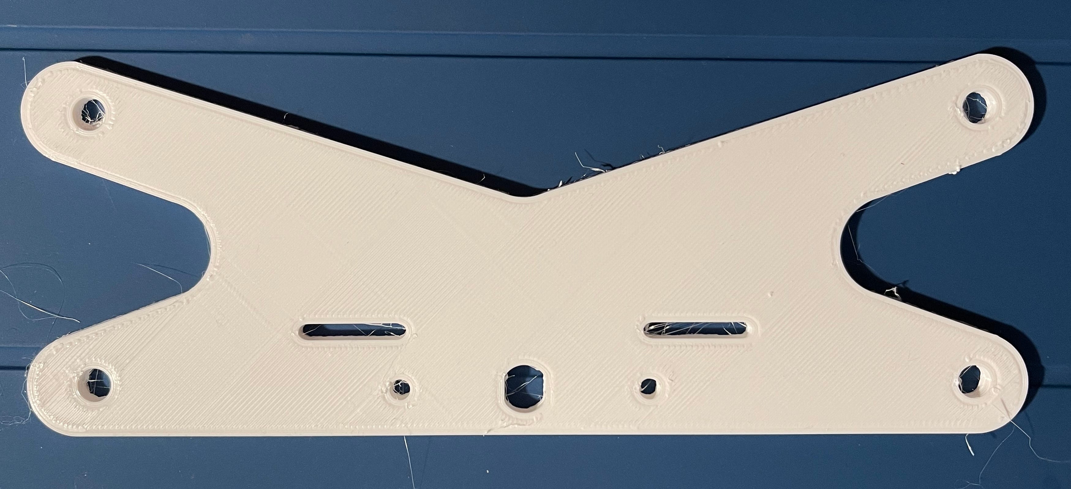
I decided to create my own. It’s posted here on Tinkercad where I designed it, and also uploaded to here on Thingiverse. It’s dimensions are roughly 200x75mm, but you can scale it however you like. (I recommend only scaling X and Y and leaving Z alone.)
It contains the following holes:
standard BNC chassis mount
#6 screws for adding posts to connect your elements
additional holes for hanging
some flat holes intended for velcro straps.
The design is CC BY-SA, so please give me credit if you publish a derivative.
Connect the BNC ground tab directly to a ring terminal and solder it. You need to make sure the ring terminal lines up with the hole in your wire winder. It’s tricky, but not impossible.
Attach hardware for posts. I use 2 regular washers and 1 lock washer per post.
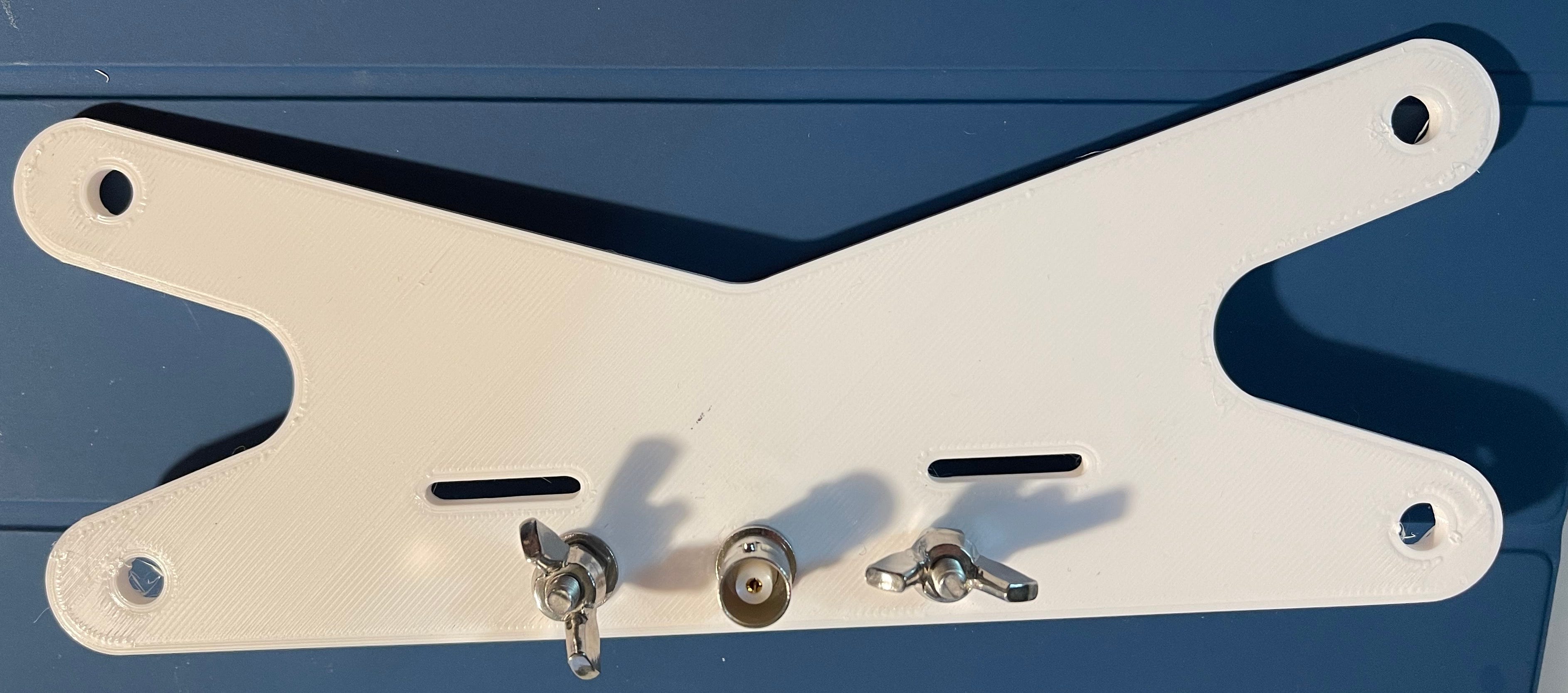
Crimp and solder a 1.25” piece of #20 wire to a ring terminal and then to the center pin of your BNC connector. Measure for fit before you crimp and solder. If you use a bit of your enabled magnet wire make sure to remove enamel from the ends.
Attach hardware for posts.

The winder is done. Let’s move on.
The Ground Plane
Cut of three 10 ft pieces of your antenna wire. Crimp them into a single ring terminal. Solder and add shrink tubing for stability.
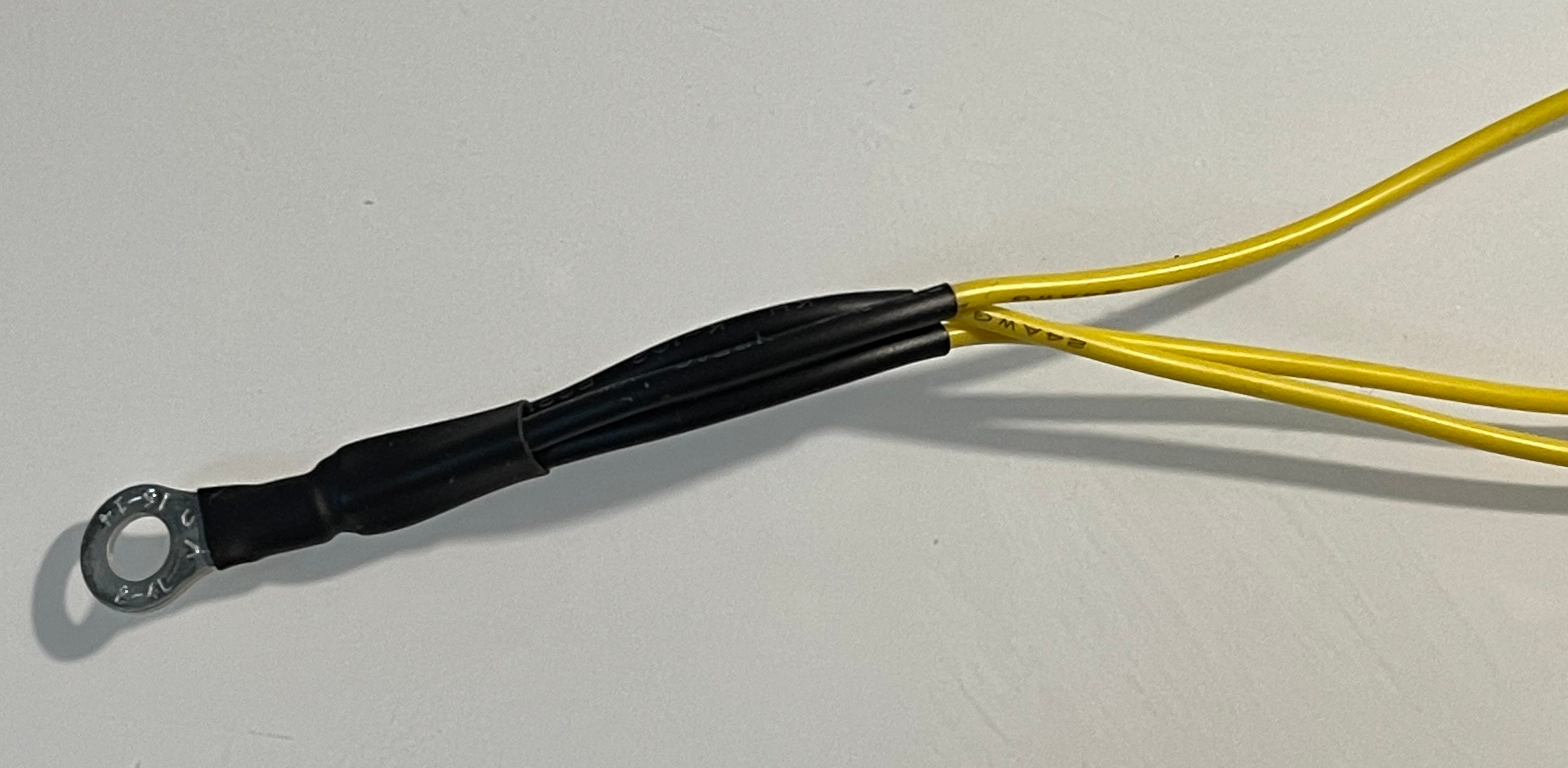
I decided to keep the ground plane simple. I know more is better, but this setup is intended to be lightweight and portable. I want to make sure it works using a minimal amount of radials.
10 Meter Radiator
Online calculators suggest a radiator for 28.1 MHz should be 8 ft 3.9 in long. For this particular wire, I only needed 7 ft 5 in, suggesting its velocity factor is around 0.76.
If you don’t know the velocity factor of your wire, just cut it long (8.5 ft or so) and trim until your antenna analyzer says you’ve got it dialed in. (Make sure you measure with the radials attached.)
Attach a ring terminal and any shrink tubing you might want.
10 Meter Trap
The normal approach to building a trap is to use a few calculators to determine how many windings you need for your toroid to get to your desired inductance.
I’m going to do the math once for 10 meters, then leave it as an exercise for you for every other band. Remember these two formulas?
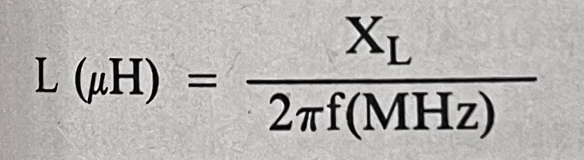
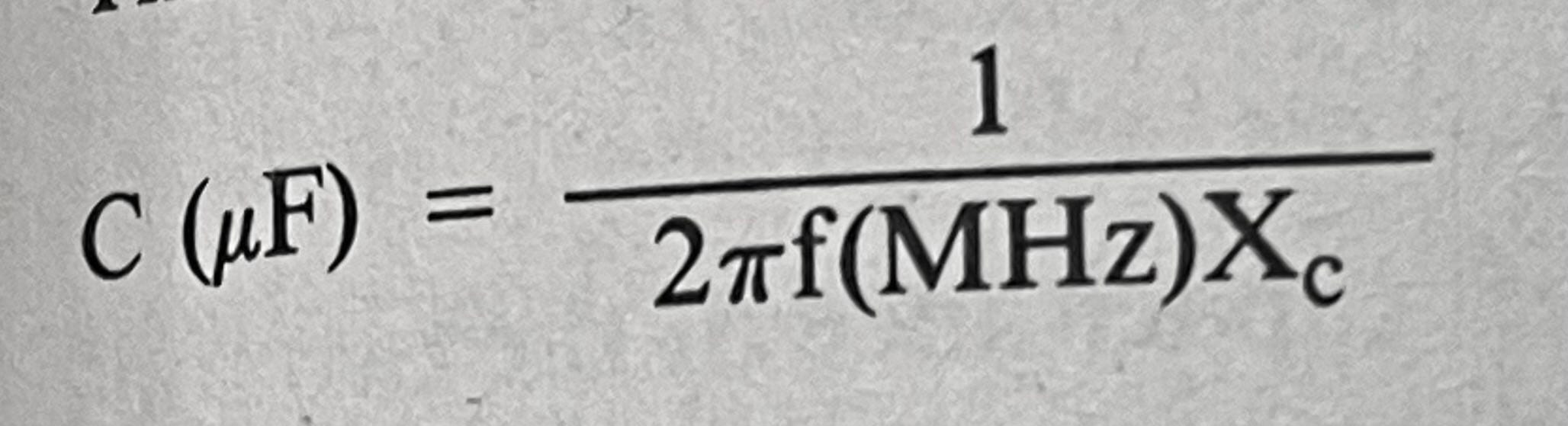
We’re going to use the heck out of them.
First, assume an ideal X of 200 ohms. This allows you to solve for L and C of 1.13uH and 28.32pF respectively (I’m playing fast and loose with uF and pF here). Since I don’t have a 28.32 pF cap, but I do have a 27pF, I’m going to recalculate my reactance by solving the bottom equation for XC with C=0.000027, giving me 209.77 ohms. Close enough.
The rest of the math here isn’t hard since you know that XL=XC=209.77, f=28.1 and C=27pF.
Plug that into L=XL/(2𝜋f) and we arrive at an inductance of 1.188uH (not far off from our original optimal value of 1.13uH).
The calculator from the kind folks at kitsandparts.com tells us we need 17.2 turns on our toroid. (The math for calculating turns isn’t hard either, but assumes you know a thing or two about the characteristics of the toroid you’re using, namely that it’s AL is 4).
I will tell you this now: I only needed 16 turns. Read on to learn how to figure that out…
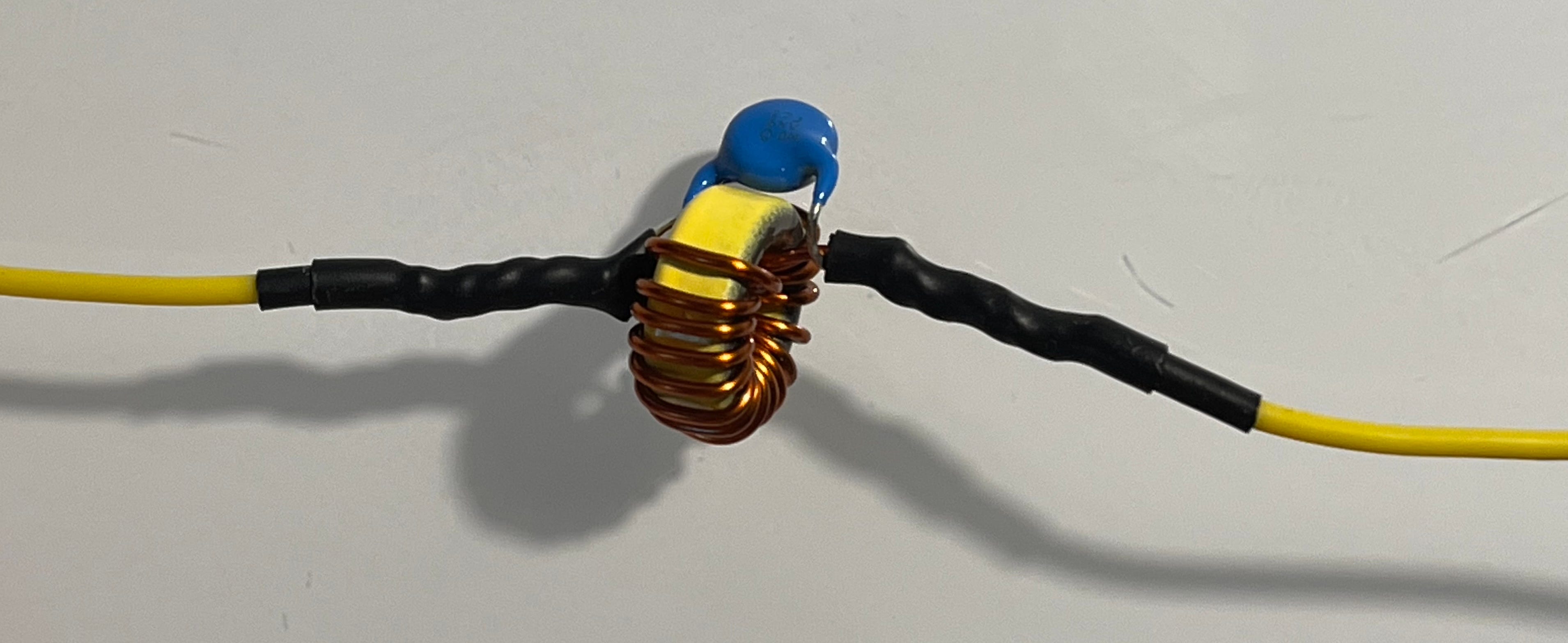
What you’re looking at is a T50-6 toroid with 16 windings of 20 AWG magnet wire and a single 27pF capacitor.
Tuning a Trap
There is often a difference between the theoretical values derived from our equations ant the actual values that work best in the field. In this case, it’s the difference between the 17.2 turns called for and the 16 turns I actually used.
Note: you can measure the resonant frequency of a trap using a small loop and your NanoVNA, but I’ve found that only gets you in the neighborhood. It’s more effective to take the number of windings called for by the math, round up, attach to the antenna, measure, then adjust.
In this case, the first reading was lower than 28.1 suggesting I had too much inductance. My options at this point were to a) remove a turn from the windings or 2) spread the windings apart (either of these will move the resonant frequency up). (Conversely, tightening the windings increases inductance and will lower your resonant frequency—this comes in handy during tuning.)
From a practical standpoint, it makes sense to first try adjusting the spacing of the windings. In my case, it didn’t get me up to 28.1, so I removed one winding. That ended up being too much (antenna now resonated too high), so I tightened the windings a bit. Eventually I got it dialed in at 28.1 MHz. 10 meters was now perfectly dialed in.
In theory, you shouldn’t have to adjust the lower bands once you’ve got a trap dialed in.
15 Meters
The next band was 15 meters. I selected 21.1 MHz as my target.
I added wire to the last toroid that brought an additional resonance dip at 21.1 MHz. While I had the antenna analyzer attached, I measured again for 10 meters (28.1 MHz) just to make sure things didn’t go whacky. I needed 1 ft 10.5 in of wire to get to 21.1 MHz.
Next was the 15 meter trap. Math suggested my optimal L and C of 1.32uH and 33.02pf respectively. I settled for C=37pF and eventually arrived at 19 turns around the same T50-6 toroid. You can see the trap I ended up with below which uses a 27pF and a 10pF cap connected in parallel.
This trap was tuned to 21.1 MHz using the same trial and error approach I described for 10 meters.
20 Meters
All that remains for 20 meters is to add enough wire to bring it into resonance for my targeted frequency (14.1 MHz). That took exactly 4 ft.
That’s it. You’re done. Go play radio. Read on if you want to learn about some of the pitfalls…
Some Pitfalls
Air Coils
My first attempt at building this antenna called for me using air coils. I never did figure out what I was doing wrong. Perhaps the coil was making the antenna look longer. Perhaps I just hadn’t figured out the trap tuning process yet. I don’t know. Of course, this was all before I learned about the ideal 200 ohm reactance, so that could have been part of my problem.
Bad Reactance
If you don’t have the right combination of capacitors to get somewhere close to the ideal C, you may be tempted to stick in 100pF and recalculate for L. Do this at your peril. You’ll have a more difficult time tuning the trap as your reactance gets further and further from 200 ohms.
Measure, Measure, Measure
Once I settled on using toroidal traps I quickly realized that if I did a step and didn’t go back and measure everything (including for the frequencies I had already verified), something would invariably get out of whack. Take it easy, go slow, and measure everything after you make any kind of adjustment. You’ll a) learn more and b) save time. And make sure to keep that NanoVNA charged!
Next Steps
This antenna can be easily deployed using my 20 ft fishing pole.
By the time you’ve read this, I will have already completed a similar antenna for 12, 17 and 30 meters. Six bands with two antennas and no tuner is a potent setup in my opinion. Based on how I operate, the only band it lacks is 40 meters which could be solved by adding an extension to either antenna and run in an inverted V configuration.
If testing goes well, I’m going to build one each for 100 watts as well. I’ll adjust the resonant frequencies up a bit to target the phone portion of each band, use a bigger toroid (T90-6) to account for the extra power, and heavier wire (20 ga). It’ll be fun.