Base-Loaded 40 Meter Coil Revisited
How I forced myself to learn Autodesk Fusion and why you should to.

Lessons From Time
A few years ago I shared a post about building base-loaded coil from copper and PVC. It was essentially a knock-off Sporty 40 made by Wolf River Coils, whose storefront was shut down at the time. By far, it is the most visited post on this blog.
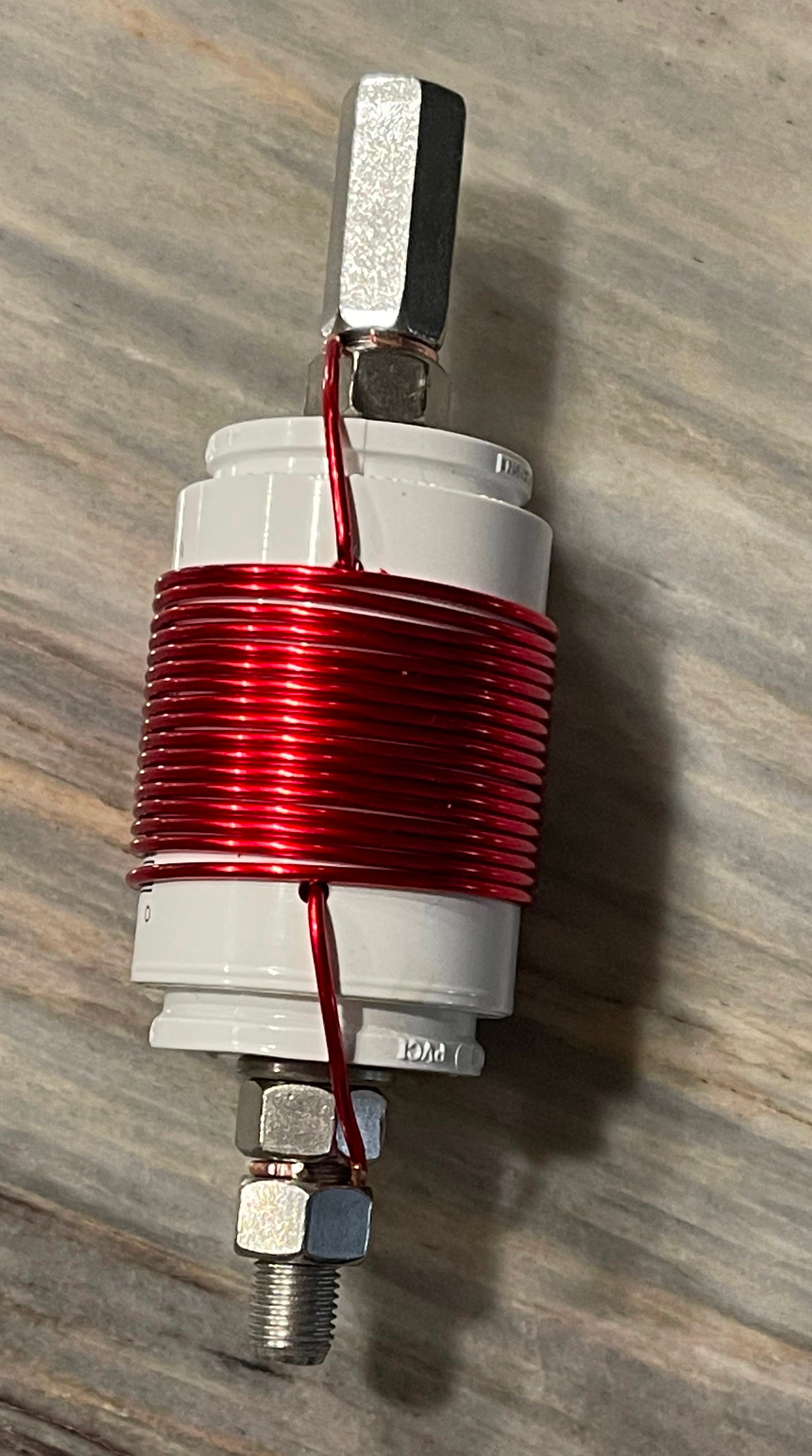
Between then and now I’ve learned a few things about all these coils. I’ve gotten a better handle on how form diameter, coil composition (e.g. steel vs copper), and turn spacing (or pitch) impact the quality and performance of a coil. Let’s talk about these things…
Stainless Steel vs Copper
I knew as much coming in: copper would turn less of my watts into heat than stainless steel due to its lower resistance.
However, using copper comes at an apparent cost. It behaves less like a dummy load when compared to stainless steel. This means that stainless steel will look better by showing broader bandwidth or a prettier SWR curve vs a comparable copper coil. That’s a tough pill to swallow.
There would also be a difference in Q in favor of copper were you to measure it. In fact, copper would show significantly higher Q than a comparable stainless steel coil. Radiation efficiency would also be better with copper. (Higher Q is better for RF purposes.)
These things would all contribute to a better operating experience especially when operating using modes that require higher duty cycles (think: FT8 or CW).
In short: copper may give a sharper, fussier SWR curve while actually putting out a stronger signal when compared with a similarly constructed stainless steel coil. If you’re using a stainless steel base loaded coil, go touch it after running FT8 at 50 watts. That warmth you feel is power that didn’t make it into the air.
Here is some background reading.
Turn Spacing, or Pitch
This is one thing I got wrong with my original design. Keeping the turns tight does indeed increase inductance (and we want inductance!). But having tight turns also encourages stronger mutual magnetic coupling and increases proximity effect. The magnetic field from neighboring turns forces RF current into progressively smaller portions of each conductor’s surface, increasing its effective AC resistance (this is bad).
Altogether this means lower Q, more heating, and if you can believe it—more sensitivity to things like nicked enamel, dirt on the coil and slightly irregular spacing. Not what you want in hand-built coils.
This was born out in the coils I sold. I received a few back that clearly weren’t working, even they they appeared to be constructed just like any other. I could never figure out what was going on with them, and now suspect it was just random stuff like this.
Ok. Let’s Do This Better
I landed on the idea that moderately spaced copper would be my best-performing choice. However, I wanted to end up with something that a) hobbyists could easily build, and b) that I could still make and sell on my own. I don’t have the CNC equipment to turn out custom forms.
So here’s what I ended up with:
Copper. We must continue to use copper.
Keep the PVC form. It’s sturdy even though it starts to soften somewhere between 60º-80º C.
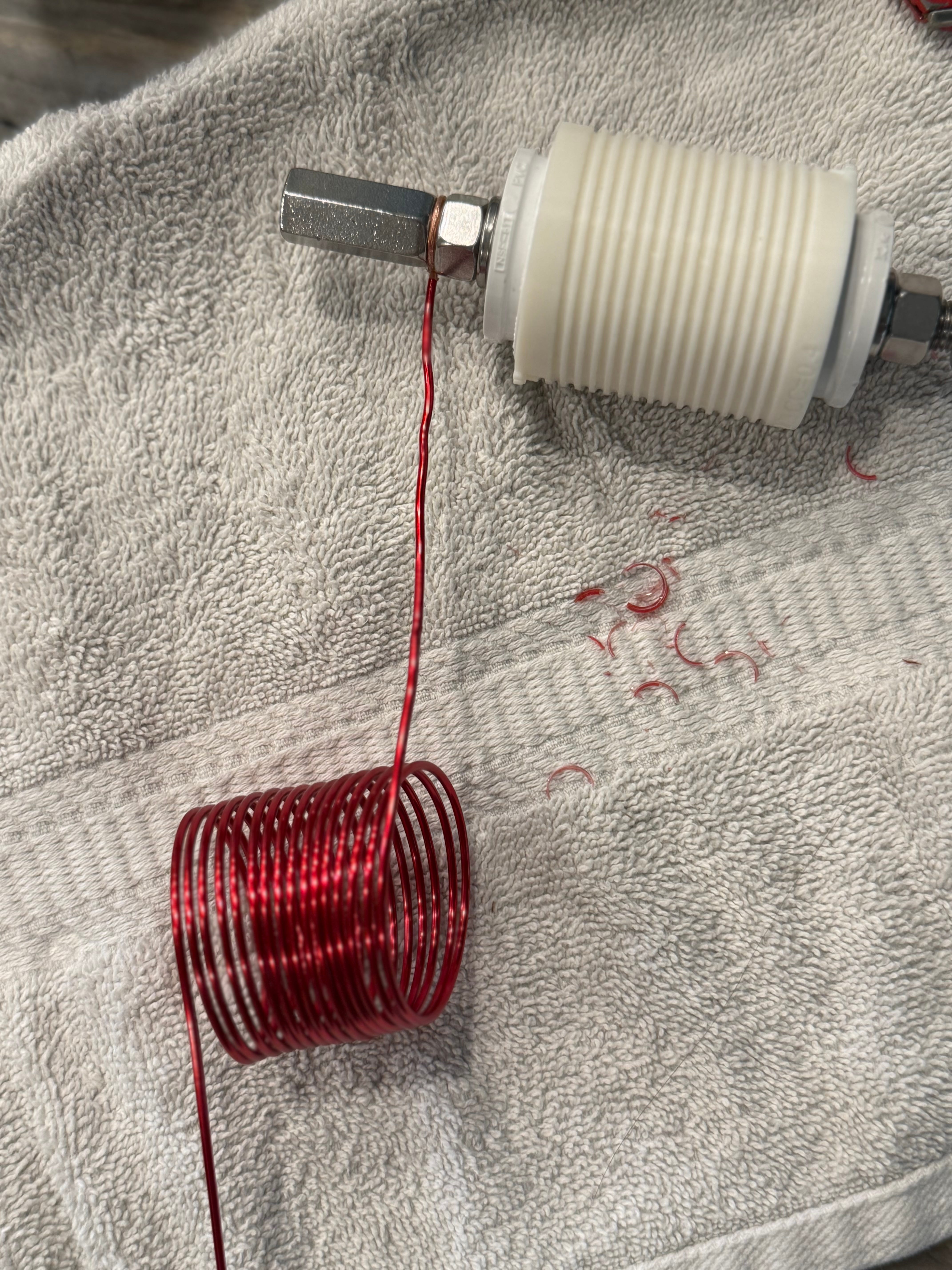
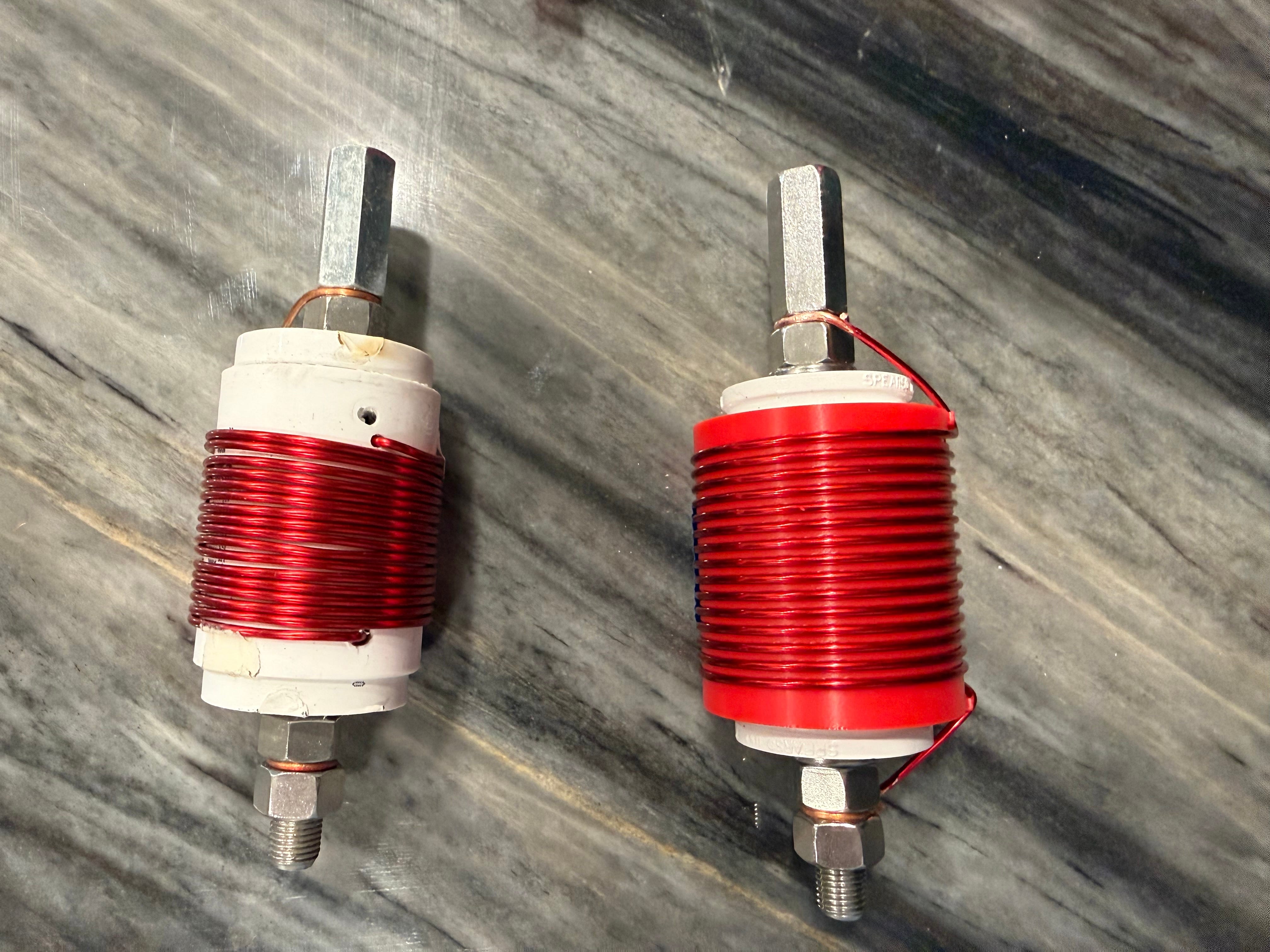
Cover the PVC form with a 3D printed sleeve that ensures consistency, even spacing and offers some protection from heat. I spent several weeks confronting my demons and finally learning Autocad Fusion (formerly Fusion 360) to create this.
I’m still testing out the differences between ASA and PETG for the printing material. ASA has a higher softening point (95º-110º C) vs PETG (75º-85º C). Both beat PVC though (60º-80º C). I’d like to see if I can get away with using PETG because it’s easier to work with after printing as it is more flexible and does not contract as much as ASA.
The next step will be to wire them up and see if I can send 75-100 watts of FT8 out into the aether without a [literal] meltdown. I’ll get on that this week.
Retrofits!
A neat bonus is that with current dimensions anybody with a couple wrenches should be able to take a single sleeve and retrofit it over a v1 coil and have about 2.5 inches of wire left over. Expect a future post with instructions.
Next Steps
It was getting to be time to put together the next batch of coils anyway, so this timing is good. Parts will arrive this week as I’m building and testing a handful of prototypes.
When everything is complete I plan to update my sales channels (Square and Ebay) with new items:
A new 40 meter coil (the ‘v2’) suitable for 17 ft whips,
A retrofit sleeve for existing customers (pay only shipping)
A sleeve for anybody to buy.
Eventually, a 40 meter coil suitable for use with the 25 ft whips, which are becoming more popular.
The bad news is that I’ll need to raise prices a few dollars**. Since I started out the costs of everything (materials and postage) has gone up around 10 percent.
Current STLs of the sleeve are already available on Tinkercad and will eventually be available on Thingiverse. I plan to maintain them as the coil forms evolve.
Thanks, that’s it for now. I need to go take something off the 3D printer.
** Prices will go up more for the Ebay versions. For whatever reason Ebay customers return more units and the cut Ebay takes is astronomical. If they weren’t responsible for a third of my business, I’d be done with them altogether.
Ok. If you’re still reading, here’s a picture of me and the family at Yellowstone this summer. We had a wonderful time. I did a little bit of POTA while I was there but made the classic blunder of having a brief activation that was spread across two UTC days. Eight contacts in one day, seven in the next. 😒